Power Electric Equipment
AUTOMATIC TRANSFER SWITCHING EQUIPMENT
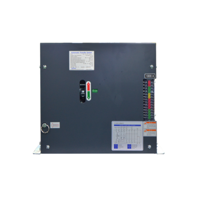
ATSE OSEMCO Automatic transfer switching equipment has used internal quality programs to help exceed our customer needs for product quality, service, and support. O-Sung Electric Machinery co., ltd corporate commitment to quality is evident in our ISO 9001 registration. The scope of OSEMCO’s registration includes design, manufacture and service of equipment for electrical apparatus used in the power generation industry. transition loads between normal and emergency power sources with open transition or closed transition options. The specific functions performed by a given load and the importance of those functions to safety or security play an important role in determining which kind of transition is required. There are three main classifications of ATSE : open transition, closed transition, and open and closed withdrawable Bypass-Switch design transition.Manufacturer of the “OSEMCO” Automatic Transfer Switching Equipment that are tested and verified according to IEC60947-6-1 and UL1008.
• True Double-Throw Contact, PC class
• Range 100 – 6300 Amps, 600 VAC, 3 or 4 Pole, 50 or 60 Hz
• Open Transition, Close Transition and Bypass-Isolation Switching
• Solenoid Operating Mechanism
• Solid, Switched, or Overlapping neutral
• Contract Transfer Time less than 100 milliseconds
• Contact use Silver-Alloy Composition
• Mechanical Interlocks prevent unintended operation
• Withdrawable Bypass-Switch design allows for easy transfer switching maintenance
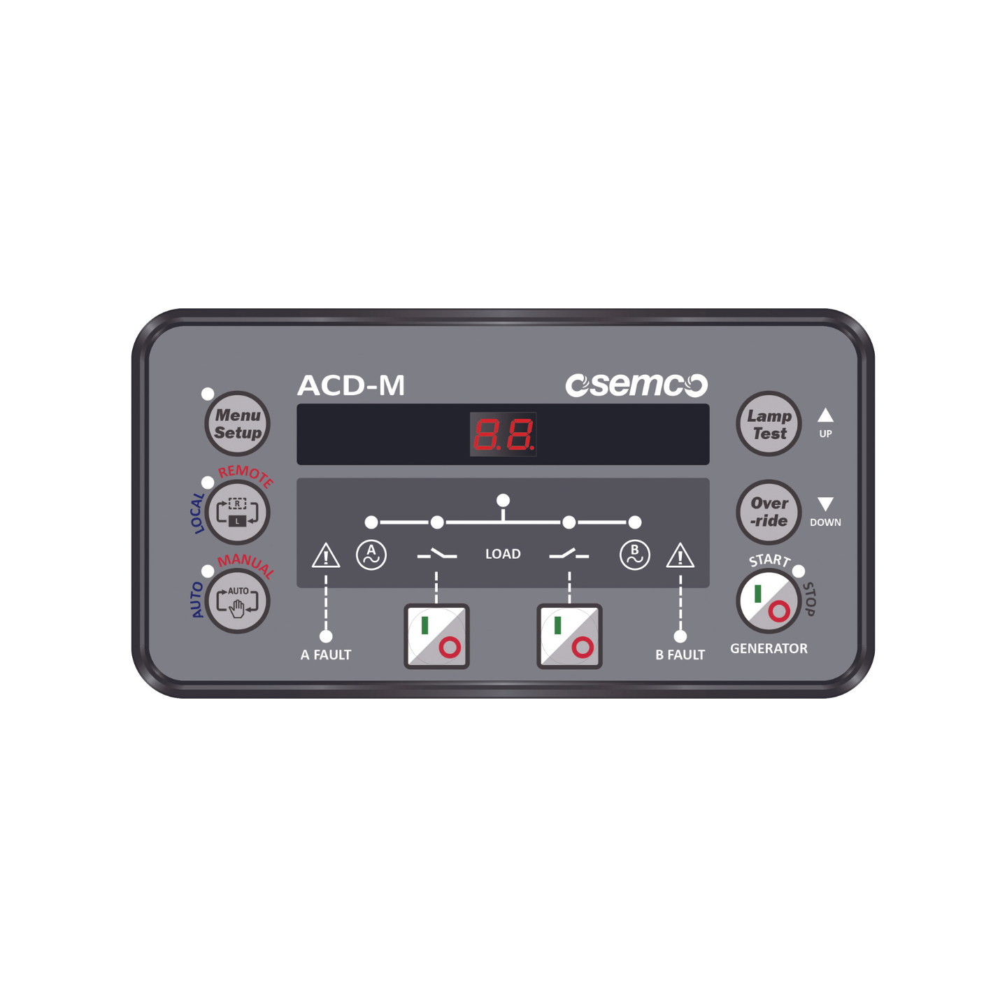
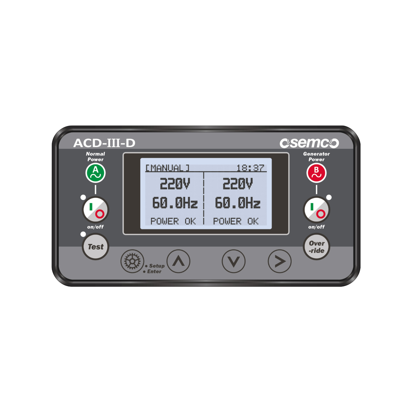
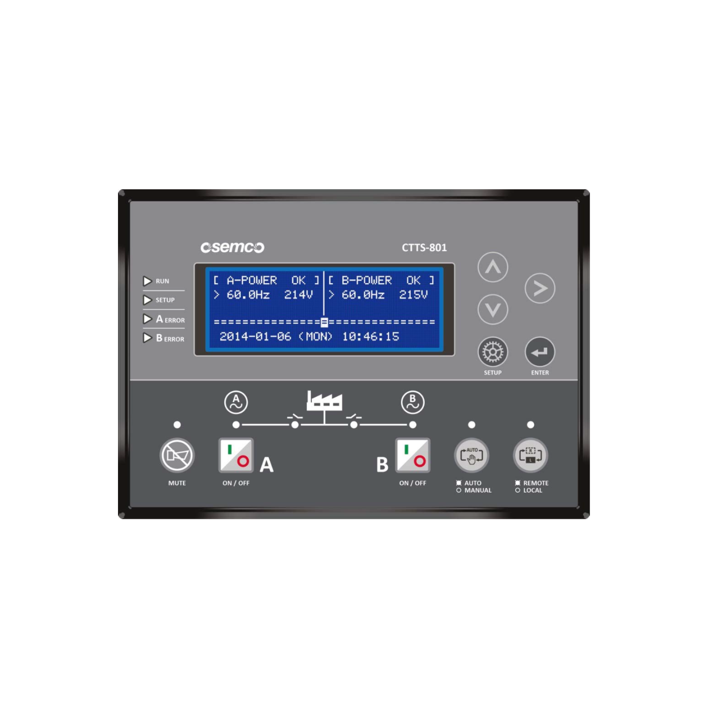
• Microprocessor Controller with keypad and LCD Display
• Local/remote communications capability for interfacing
• Fully warranty ATSE and Controller Unit by OSEMCO
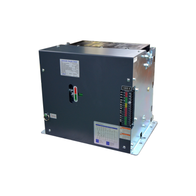
OPEN TRANSITION
– Open transition is a break-before-make transfer. Available in 2 positions [ ON-ON Type ATSE],
Direct transfer method A ⇒ B, B ⇒ A instantaneous transfer can be performed by operating signal.
A ⇒ B, B ⇒ A or 2 positions Type ATSE has additional function of Overlapping Neutral Contact.
– Open transition is a break-before-make transfer. Available in 3 positions [ ON-OFF-ON Type ATSE],
open transition break before make configuration and are designed to provide transfer of loads between two power sources with adjustable time or without time load disconnect position.
A ⇒ Off ⇒ B, B ⇒ Off ⇒ A, and A ⇒ Off ⇒ A, B ⇒ Off ⇒ B And also, Safe and easy manual operation for 3 position switches using maintenance handle.
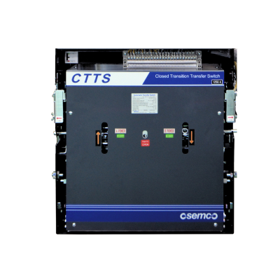
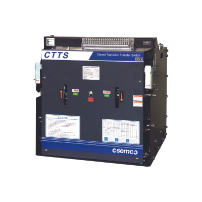
CLOSE TRANSITION
– Closed-transition (CTTS) is an uninterruptible switching method that switches between the two power sources at the same time when A-power sources and B-power sources are used.
– Closed-transition transfer switches provide a “make-before-break” switching action and utilize a momentary paralleling of both sources (<100ms) during the transfer period, when both sources are available. Both sources must be synchronized (phase, voltage, and frequency) before momentary paralleling them. Closed transition transfer switches do not include mechanical nor electrical interlocking of sources. Since there is no gap between disconnecting and connecting sources, downstream loads receive continuous power throughout the transfer process.
– The synchronous condition is a switch system that switches between uninterrupted parallel operation (within 100 ms) and uninterrupted transfer when the phase voltage difference of both power sources is less than 10 V, the frequency difference is less than 1.0 ㎐, and the phase synchronization angle is less than 5 degrees. Can be protected.
– The other power supply should be opened within 0.1 second (100ms) after switching the load from one power source to another power source by overlapping both power sources with correct synchronization.
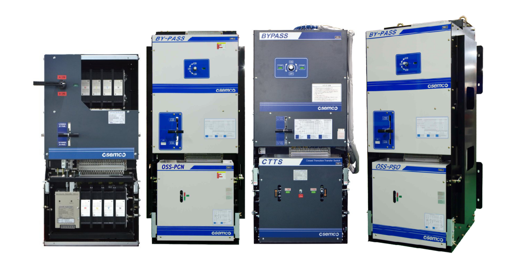
ATSE WITHDRAWABLE BYPASS-SWITCH TRANSITION
– ATSE withdrawable Bypass-Switch design is systematically attached to the main ATSE, allowing operation without interruption during the repair or inspection of the main ATSE withdrawable Bypass-Switch is a mechanical interlock for preventing confusion with the main ATSE; it is an additional manual operation switch. Facilitates easy maintenance, testing, or replacement of the ATSE unit. Enables the ATSE unit to be safely removed without disrupting the power flow. Cannot Have Shut Down (24 Hr X 365 Days Operation). For Testing Emergency System Without Load Interruption. For Load that required very high reliabilities such as Data Center, Banking, Telecommunication, Hospital and Airport.
– A specialized component in advanced Automatic Transfer Switching Equipment (ATSE) systems. It provides enhanced flexibility, safety, and operational efficiency by combining the functionality of a standard bypass switching with the ability to physically withdraw or isolate the ATS from the power circuit for maintenance or replacement. An ATSE withdrawable Bypass-Switch design is installed in parallel with the main ATSE. When ATSE inspection is needed, power is supplied, and the main ATSE is withdrawn through ATSE withdrawable Bypass-Switch so that power is continuously supplied.
– The interlock circuit is configured to allow the bypass switch to move in the same direction as the main ATSE operation position, so it can prevent accidents caused by system short circuit.
– The reason to employ a bypass is directly linked to the maintenance of the ATSE in charge, as it allows to replace potentially failing parts while keeping the sources power on. Such bypass may be single or dual, depending on the possibility to use the power respectively from a unique or two sources during the maintenance. We can distinct the basic need of replacing faulty parts such as the controller, the power supply, the mechanism or the power poles of the ATSE from the most forward-looking approach of foreseeing failures through predictive maintenance.
– The traditional bypass, being built on multiple components and connections, need to be serviced on its own and may not be always in the perfect shape when you need it. Consider that in fact it is not always possible to ensure that the bypass works properly until its use is required as testing it would affect the ATSE circuit continuity itself.
CONTROLLER